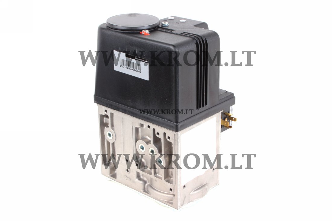
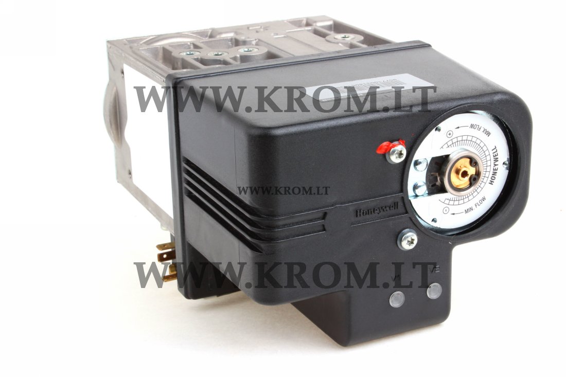
Honeywell VR434VE5039-1100 servo-combi gas valve DN34 230V IP54 Viessmann


TNT delivery service
Pick up in our office
Invoice payment
Cash
The gas valves of the Honeywell model VR434VE5039-1100, equipped with servo control, belong to class "A" and are designed to control the supply of gaseous fuel to various gas burners, atmospheric gas boilers, melting furnaces, waste incinerators and other gas-consuming devices.
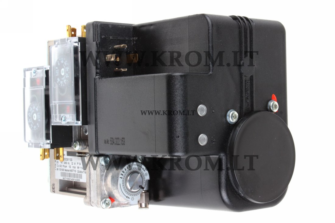
These combined gas valves can be used both in systems with spark ignition of burners (DBI) and in systems with pilot burner (IP). As standard, the gas valves of the VR434VE 5039-1100 model from Honeywell are equipped with two main valves - V1 and V2:
1. The V1 safety valve ensures quick opening/closing.
2. The second valve (V2) can work with both fast flow control and slow flow control and adjustable opening.
A pressure control valve is located between V1 and V2. The CVI valve body of the Honeywell VR434VE5039-1100 has 4 flange connections on both sides for the installation of the following equipment:
- Inlet pressure switch from the C60VR series.
- Intermediate pressure switch from the C60VR series.
- Valve inspection System (VPS) + pressure switch.
These additional components can be installed at various points in the housing of the Resideo VR434 VE 5039-1100 gas solenoid valve for optimal operation and adjustment of the system according to the requirements of a specific application.
Technical specifications
• Body material: Aluminum alloy, injection molding
• Strainer: fine mesh mesh (diameter 0.34 mm), AISI 303 steel, can be cleaned by unscrewing the inlet flange screws. Meets the requirements for mesh filters according to EN 161.
• Closing spring: AISI 302 steel
• Valve plunger: with Fe 360 coating
• Seals and gaskets: hydrocarbon-resistant types of butadiene-acrylonitrile (NBR) and viton rubber.
• Minimum adjustment capacity: 1 m3/h.
• Maximum operating pressure: 200 mbar
• Valve classification: Class A + A according to EN 126/EN 161
• Regulator classification: Class C according to EN 126/EN 88
• Supply voltage: mains 230 V~, 50/60 Hz
• Other voltages – on request.
• Ambient temperature: -15 ... 60 °C
• The flange kit contains:
1 flange with sealing plug
1 O-ring and 4 screws
1 pressure measuring fitting installed
• Housing: IP 40
Design and principle of operation
Servo-controlled combined gas valves of the VR434VE5039-1100 series are double fault-tolerant shut-off valves of class A.
The valve is opened by excitation of two-position direct-acting actuators. Each actuator consists of a coil and a locking sleeve assembly. Inside the locking sleeve there is a plunger, which is connected to a rubber valve and can move up and down, thereby opening and closing the valve. The plunger is covered with antifriction material. The flow is regulated by means of a variable stroke of the plunger. A strainer made of AISI303 stainless steel is installed between the inlet flange and the main body. The closing spring of the valve is made of AISI302 stainless steel. Seals and gaskets are made of hydrocarbon-resistant butadiene-acrylonitrile (NBR) rubber according to DIN 3535 and EN 291.
The VR434VE5039-1100 valve is a servo system.
The control valve is located between two shut-off valves. When power is supplied to both actuators, the "servo gas" begins to flow through the regulating membrane system. From this chamber, the gas passes into the servo chamber through the intake diaphragm (restriction). The pressure in the servo chamber is regulated by a pressure regulator. The balance between the servo pressure and the pressure under the control membrane determines the opening of the control valve. As soon as the control valve opens, the exhaust pressure generated by the VR434VE5039-1100 series valve will be perceived by the regulator membrane through the feedback channel. When the force generated by this pressure is greater than the value set by the adjusting screw, the control valve opens, somewhat relieving the operating pressure. This reduces the force directed towards the action of the spring of the control valve, allowing the latter to close proportionally. Thus, the control valve limits the exhaust pressure (pressure applied to the burner) to the set level. As a result, the exhaust pressure is continuously maintained by comparing it with the set pressure and changing the position of the control valve accordingly. This means that regardless of the fluctuations in the intake pressure, the exhaust pressure remains unchanged. When disconnected, a small volume of working gas from the regulator and the membrane chamber exits into the main exhaust chamber. The reference pressure feedback channel then regulates the exhaust pressure by compensating for the difference between the air pressure in the combustion chamber and the pressure at the valve. If pressure adjustment is not required, the regulator spring can be blocked by screwing the adjusting screw until it stops or until the pressure regulation stops. In these cases, the full pressure of the "servogas" opens the control valve as much as the pressure drop will allow.
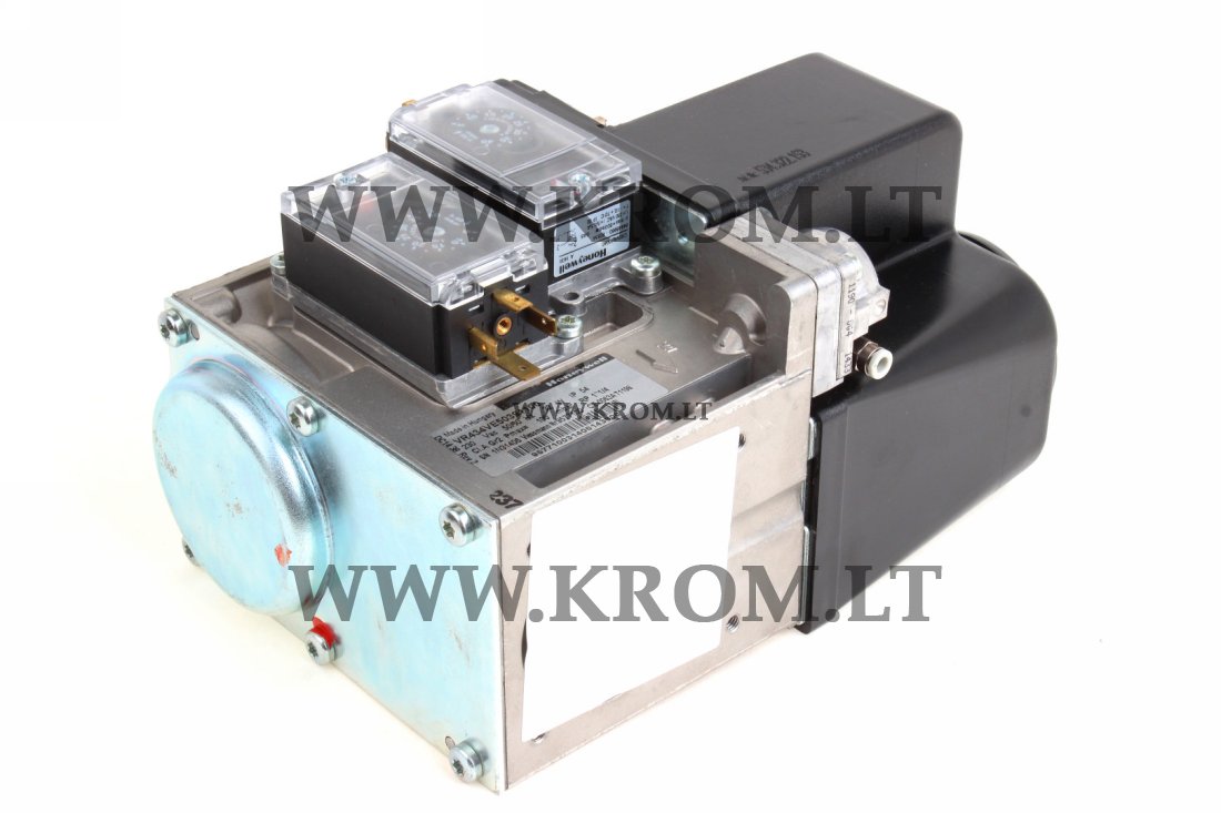
Pressure measurement points
The Honeywell VR434 VE 5039-1100 gas regulator has a number of connection points for pressure measurement, pressure switch installation or IP applications.
The following pressures can be measured:
• P - kindling gas
• 1+2 - inlet pressure
• 3 - intermediate pressure
• 4 - exhaust pressure
The corresponding numbers are indicated on the sides of the valve.
Exhaust pressure adjustment
• Open the pressure feedback connection (if provided).
• Supply power to both electrical actuators to ensure that gas is supplied to the burner.
• Check the gas supply to the installation by means of a gas meter with a clock mechanism or by means of a pressure gauge connected to the outlet pressure measuring fitting.
• Unscrew the pressure regulator cover screw to open the pressure regulator adjustment screw.
• Slowly turn the adjusting screw with a miniature screwdriver until the pressure gauge shows the required burner pressure. Rotate the adjusting screw clockwise to increase the burner pressure, or counterclockwise to decrease it.
• To exit the control mode (low pressure gas), turn the adjustment screw clockwise until it stops.
• Replace the pressure regulator cover screw.
• Restore the pressure feedback connection (if provided).
Standards
With regard to electrical safety, VR434VE 5039-1100 valves can be used in devices conforming to the European standards of the EN 60335 series, which establish requirements for
The Resideo VR434 VE 5039-1100 gas valves also comply with all electromagnetic compatibility standards for non-industrial and industrial installations.
Replacing a Honeywell VR 434 VE 5039-1100 servo-combi gas valve DN32 is a good solution to make your equipment work again. We offer a wide range of Honeywell spare parts for burners, gas trains etc. We supply original Elster (Kromschröder) & Honeywell (Maxon) products.
If you have any queries about Honeywell VR400 gas valves or any other Honeywell spare parts, please write us at 624burner@gmail.com, quoting the item code VR434VE5039-1100.
- Commodity code 84819000
- Country of origin HU
- EAN code 4046911029651